|
 |
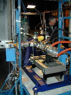
| Front
view of the Test Stand |
A
closer view of one of the eight flex joints. The big advantage
is their hysteresis free behavior. This makes it possible to even
measure loads in the range of one Newton with a precision of 1
% (remember, this is a 100 kN Test Stand !) |
 |
 |
| Detail
of one of the flex joints. It is made of heat treated special
steel, grinded and plated with electroless nickel. |
Detail
of the thrust collector. The collector allows to mount the igniter
of the booster just before firing. |
 |
 |
| Detail
of the feed through. The load cell can also be mounted on this
side of the load cell mounting block. |
The
25 kN load cell. For larger boosters the cell can be exchanged
by a larger 100 kN cell using the outer threaded circle. |
 |
|
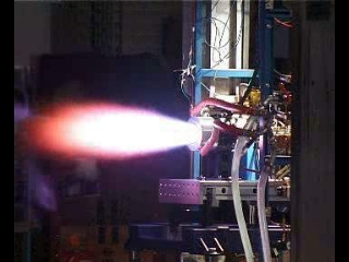
Ignition!
The picture shows a test run with the first LOX engine under rel.
low chamber pressure (o.6 MPa) using LOX/ethanol at an O/F of
1.3. In this test, the injector was equipped with only 3 injector
elements (see news 1st September 02 and 11th March 02) . Tests
with full chamber pressure of 2.5 MPa will be conducted as soon
as we have finished the muffler system. |
An
overview of the test setup. One can clearly see the frozen LOX
line and LOX valve, the regen. chamber with it's feeding lines,
the torch igniter and several thermocouples. The LOX tank is on
the top left.
|